Armed Guard G Force Alarm Evaluation for the GL1800
Armed Guard
63025 O.B. Riley Road, Suite 5
Bend, Oregon 97701
Factory Direct ORDERS 24 HOURS 800-536-7852
International Orders 541-322-5680
Fax Orders 971-231-2465
Manufacturer website http://www.armedguard.com
Fred Harmon March 8, 2004
Distributed in USA by:
Big Bike Parts
Electrical Connection
In Canada, exclusively by Parts Canada/Power Twins.
Armed Guard products are also available in Australia, New Zealand, and several other countries.
Honda GL1800 Kit MSRP $224.95 Manufacturer #GF200-HON2
• Electrical Connection # GF200-HON2
• Big Bikes #13-301
• Parts Canada #374621)
Perimeter Sensor $45 Manufacturer #AG-RADAR
Pager Module $125 Manufacturer #AG-PAGER
This is the newest G-Force, version 318B, and is the sixth generation alarm Armed Guard has manufactured for motorcycles, (since 1993). The electronics are ruggedized and epoxy potted, and all components are covered by a 5 year replacement warranty. Armed Guard claims an alarm failure rate of approximately 1% of G-Force kits shipped.
Armed Guard Security manufactures plug fit systems for Honda, Yamaha, Harley-Davidson, Kawasaki, Lehman Trike, Viper and Indian motorcycles. They are OEM alarm provider for several manufacturers.
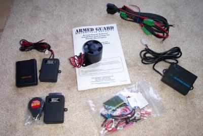
Kit Contents:
-G-Force Alarm Module w/remote transmitter. 4 billion rolling codes. 100' range.
-125db siren
-Plug fit GL1800 harness. Connects to battery, starter button circuit, and both blinker circuits. Provides flashing lights, starter disable, and saddlebag monitoring.
-installation fittings pack
-GL1800 installation instructions
The standard G Force alarm kit comes with the alarm module, remote, siren, status LED, various connectors, and a specific GL1800 plug fit wire harness. Optional features include the Radar Perimeter Sensor (#AG-RADAR) and Pager Module (#AG-PAGER). Each comes with their own connections to hook them to the main alarm module.
Upon inspection, the wire harness appears to be of a high quality, has all the proper connections for the GL1800, and is covered with a wire loom that results in a much nicer looking finished installation.
The G-Force Alarm module itself is a potted module, which means it is totally waterproof. The pager transmitter is also potted and waterproof. The perimeter sensor is not potted, but normally it gets mounted higher up on the bike either in the trunk or behind the passenger backrest where water is not an issue.
System Operation
The remote has two buttons on it. If the first button is pushed, the system and perimeter sensor becomes armed or if the second button is pushed, the system is armed, but the perimeter sensor is not armed. Pushing either button again disarms the system. A single loud CLICK is emitted when the system is armed and the turn signals flash once. A double loud CLICK is emitted when the system is disarmed and the turn signals flash twice.
The alarm module monitors the bike voltage for any sudden drops that would indicate an attempt to hot wire the bike. It also interrupts the starter circuit with a latching relay so that the starter will not function, even if the power lead to the alarm is severed by the thief. An internal, adjustable, sensor is built into the body of the alarm to detect tilt, motion, or a sudden shock to the bike. The remote controller uses code-hoping technology that prevents someone from receiving and retransmitting the codes to disable the system. An auxiliary sense wire and circuit is also provided to monitor other inputs, like when the saddlebags and/or trunk are opened. Additional inputs can be added to this auxiliary sense wire as well.
The microwave radar perimeter sensor has an adjustable range/sensitivity and it also has a warn-away function that gives the offending party two warnings within 8 seconds to back away before the systems alarms. If no more perimeter invasions are sensed within 5 seconds, the counter resets. After the third trigger of the perimeter sensor within 8 seconds, the system goes into full alarm. The warn-away audio warning consists of three clicks and flashes of the turn signals on the first event. The second event within 5 seconds triggers five rapid clicks and flashing of the turn signals. The clicks are loud enough to startle the offender, but are not so loud as to annoy anyone nearby. Maximum range of the perimeter sensor is about 10 ft, depending on where you install it.
The pager can be set to vibrate or beep when activated. Advertised range of the pager is up to ˝ of a mile and the transmitter unit operates on the 27 Mhz frequency band with a transmitting power of 4 watts.
The unit draws 4milliamps of current when in the armed mode. The flashing LED draws another 1milliamps and the perimeter sensor adds another 12milliamps when activated. According to the folks at Armed Guard, they did extensive studies with Yuasa and Kawasaki in 2003 and have determined that the system can be safely left armed for 1-2 weeks with the perimeter sensor activated, and as much as 6 weeks without perimeter sensor activated, and the battery will remain within normal operating range. A battery tender device is recommended for any extended storage.
Installation:
Full installation photos:
http://www.pbase.com/fredharmon/gforce
For the most part, the installation instructions are very good, and include photos of installing the alarm on the GL1800.
Thanks in large part to the EC wiring harness, installing the unit on the bike is very simple, and no cutting or splicing into the bikes wire harness is needed. There are a total of three connections made to the bikes wire harness. One connection goes to the starter circuit next to battery to break the starter circuit when the alarm is active. The other two connectors go between the turn signal connectors at the rear of the bike behind the license plate panel. Two wires connect the alarm main unit directly to the battery, and the hot lead has an included 7.5 amp fuse similar to the GL1800 fuses. Two more wires connect the alarm main unit to the siren and/or pager. The wires to the siren do not have connectors on them, so they get spliced to the two wires from the alarm unit.
The first order of business is to decide where you want to locate the main unit. The instructions show mounting the unit just behind the crossover bar under the seat on top of the rear fender. This location allows you to screw the unit directly into the rear fender and this is a good location. There appears to be just enough space for the unit to sit between the rear fender and the bottom of the seat when it is installed here, as long as the unit is as close to the crossover bar as possible. However, it is entirely possible that you already have another gadget mounted in this location. In my case, I had a Mic-Mutes headset controller mounted to the crossover bar and a Kennedy PTT hack and Autocom intercom system also mounted nearby. Due to the congestion of wires and modules already in the area, I decided to search for another mounting location.
I found two alternate suitable locations. One is on the rear fender below the relay switch box assembly. The only problem with this location is that it is difficult to get the screws into the rear fender due to the angle it is mounted at. A second alternate location is on top of the gas tank to the right, and aft of, the fuel pump. The only problem with this location is that you cannot put screws into the plastic fuel tank or else you will have a nasty fuel leak. My solution was to mount it on top of the fuel tank using adhesive Velcro. This allows me to remove the module when I need to do maintenance on the bike that requires removal of the gas tank (like replacing the shock etc). There are other suitable locations as well, and the only real requirements are that the harness has enough room to reach the starter and turn signal connectors, and that the alarm module not be mounted with the sticker on the top of it facing either side of the bike in a vertical fashion. The module needs to be mounted more or less horizontal, but it does not have to be level.
Once you have the main module mounted, the next step is to start connecting the harness to the bike. I first located the starter connectors next to the battery positive terminal. This is a two-pin connector and is inside a rubber boot next to the battery. As noted in the instructions it has one green wire with a red stripe and one yellow wire with a red stripe, and the connector body should be red. There is another two-pin connector in this boot that has the same color code wires in it, but it has a white connector body. Once you disconnect this connector, it is easy to verify that you have the correct one, by simply turning on the ignition key and attempting to start the bike. If you unhooked the proper connector, the starter will not engage. Once you have disconnected the starter connector, route the portion of the EC harness over to the starter connectors and connect them to both ends of the connector you just pulled apart and push all the connectors back into the rubber rain protector boot.
The next step is to remove the rear plastic panel of the bike that the license plate attaches to. Once you have the panel off you need to route the portion of the EC harness that has the four green connectors on it for the turn signals, back to the rear of the bike. I did this by routing the cable down between the top of the rear fender and the seat on the right rear corner of the bike. Once I got the connectors pushed through the opening and forced down as far as I could, I then returned to the rear of the bike and pulled the harness the rest of the way through. Now you need to locate and disconnect the two rear turn signals connectors. They are both a three-wire connector inside a rubber boot on the left side of the bike. Once located, unplug them and connect the EC harness connectors to both ends, and put the connectors back into the rubber boot. The extra two added connectors made it difficult to get them all back into the boot, and I had to leave one out. I wrapped this lone connector in a zip lock bag to protect it from the water spray of the rear tire.
Now you need to connect the small red LED that is used to tell you the system is armed. I located mine in the same place outlined in the instructions, on the right side of the handlebars in the plastic tunnel cover, and it seemed to work well there. Do not try to put it on the left side of the handlebars as the ECM mount is underneath the tunnel cover and will interfere with mounting. I simply drilled a Ľ inch hole and pushed the led through. Then I routed the black wire to a grounding point on the frame and the red wire back to the alarm main unit. The red wire from the LED then is then connected to single the 6 inch red wire that comes out of the alarm module. I used solder and heat shrink to make the connections, but the EC kit includes crimp type connectors that can be used instead.
Next I installed the siren. The instructions show the siren mounted on the underside of the rear fender and bolted in place. I chose to route mine in the cavity between the right rear corner of the gas tank and the frame, and I used zip tires to hold it in place.
Optional Features
The last two items to be installed were the remote pager module (#AG-PAGER) and the microwave perimeter motion detector module (#AG-RADAR). Both of these features are optional, and are available through the distributors and the manufacturer directly. The pager module fit nicely at the lowermost point in the rear of the seat where the passenger back rest panel and rear fender meet. There is a rectangular recess in this space that is the perfect size to hold the pager module. (In the instructions, this is where they showed the perimeter sensor being mounted.) I fastened it in place with adhesive Velcro and ran the antenna wire up the back of the panel and into the top portion of the trunk where the trunk lock controller lives. The two red wires that activate the module are then routed to the alarm module. Now you can connect the red and black wires from the alarm module to the siren and to the pager unit. Again, I chose to solder and heat shrink the connections.
In addition to the stock 125db siren, the manufacturer offers a 125db battery backup siren (#AG-SIRENBB), as well as the really loud 129db high output siren (#AG-SIRENHO).
The last item to install is the perimeter sensor. The instructions say to mount it in a fairly high location for best results. I chose to put mine inside the trunk, at the top edge of the front trunk panel, and facing forward. This location works well and gets the module in a location where it functions properly and also is protected from the elements. There is only one cable that comes from the module, and it has a connector on the end, so you simply route it up to the alarm module and plug it in.
Additional Installation notes for the brave
Once I completed the basic installation and fully tested the unit, I decided to go one step further. I quickly discovered that the saddlebags were monitored, but the trunk was not. So the first thing I wanted to add was a circuit to monitor the trunk. This turned out to be very easy (only one wire and a diode had to be added). Also, since I sometimes carry valuables in the four small glove boxes, I wanted to be able to monitor them as well, as only one of them actually locks. This required a bit more work.
For the trunk monitor circuit, I first had to remove the rear lower panel that covers the trunk and access the wire for the switch that tells the bike when the trunk is open. This is a brown wire with a red stripe wire on connector C16 (see page 11-1 of the Honda ETM manual). I simply piggybacked a wire onto the existing one, and ran this wire down the harness to the EC wire harness that goes to the rear turn signals. I also had to add a diode in series in the wire, with the diodes anode (positive end) toward the end of the connection to the trunk circuit wire. This diode is necessary so that the graphic LCD indicator that shows you what compartment is open on the instrument panel works correctly. I then located the brown wire in the EC harness, which is the wire for sensing the saddlebag open switches, and piggybacked my new wire onto it. That completes the trunk circuit wire addition.
The glove box monitoring was a bit more involved. The first step was to go to a local electronics surplus store and pick up four micro switches that were small enough and would fit. They also had to have a Normally Closed contacts on them in order to work properly. Magnetic reed switches would also work if you could get them with Normally Closed contacts. I made some small wires for them out of some computer ribbon cable and connected them to the Normally Closed contacts. Then I installed each switch into the glove box housing so that the switch circuit would be open when the glove box was closed, and it would close the circuit when opened. I won’t go into the details of switch installation and location, as implementation will depend entirely on what kind of switches you use. One wire of each switch should then be connected to ground, and the other end should go to the brown wire in the EC harness so that the four switches are wired in parallel. When the alarm is activated, if any switch closes, it applies a ground to the brown auxiliary sense wire, which trips the alarm. Be sure to route the wires in a way that they allow you to do basic maintenance, like removing the top shelter easily. I had to add some small two-pin connectors in key locations to allow me to unplug the glove box switch wires when I need to remove a glove box, or the top shelter.
I have since learned that Armed Guard sells magnetic reed switches designed for just such purposes. The part number is #AG-MAGSWITCH and they are normally open magnetic contact switches. This would be a good addition the basic alarm system and the cost is minimal.
System Testing
The first step is to test system operation and make sure that the alarm activates. This is best done by stuffing some foam into and around the siren so you don’t go deaf and make all your neighbors hate you. You could also disconnect the siren altogether and let the turn signals tell you when the alarm activated if you wanted to. Next, arm the system and check that the alarm activates when either saddlebag is opened. If you have the pager module installed, check to see that you receive a page signal when the alarm activates. Then arm the system and try gently moving the bike to make sure that the shock sensor works. Also check to see that the turn signals flash when you arm and disarm the system and when the siren activates.
Once you verify the basic functions, arm the bike with the perimeter sensor active. You may need to adjust the small rheostat on the perimeter module so you get the coverage you desire. I set mine to the very minimum setting, which seems to be just about right. It doesn’t activate unless you violate the bikes personal space. You can easily walk directly in front of or behind the bike without it activating, but if you get near the cockpit, the countdown warn away function goes into operation.
System Performance
Ok, now that installation is all complete, just how well does it work? Quite well actually. For starters, the shock sensor has four settings that allow you to fine tune how sensitive you want the G shock sensor. It also is easy to change anytime you want, as you simply hold down one of the buttons on the remote to change the setting. You have a choice of four setting levels. This means you can set it to a less sensitive position on a windy day that might cause the bike to move slightly, or if parked anywhere that it might get set off by small vibrations (like anywhere in California in earthquake season). If activated, the system resets after 45 seconds, so it won’t howl incessantly and run your battery down if something trips it.
The siren is more than adequate and supplies all the noise you would want. At close range, the pitch and volume level is actually painful, which is good, because it will drive anyone tampering with the bike away quickly.
The pager is small and unobtrusive, (though it could always be smaller) and I have not yet been out of the range of its signal. I work in a concrete building with copper shielding in the walls, and the signal is still strong enough to penetrate through to my desk, which is better than I can say for some of the local cell phone providers with towers within a few blocks. It operates on two standard AAA cells.
The two-button remote can be connected to your key ring, is about the same size as the bikes remote (though a bit more round) and has sufficient range. The only catch is that if you have the pager function installed, the high power of the pager RF can interfere with the remote frequencies. This means that if the alarm activates, and you attempt to disarm it, it may take a few seconds for the system to disarm. This is because when the system is attempting to transmit a 4 watt page signal to the pager, it temporarily overloads the alarm’s RF receiver. It you simply count to two before trying to disarm it again, it will disarm.
All in all, the perimeter sensor option works very well. I commute on my bike and park it daily in a high traffic area right outside a gate that everyone must pass though. With the perimeter sensor activated all day long, the system has never given me a single false alarm. Traveling on a weekend outing, I parked the bike outside a restaurant while I went in to eat. I watched from the window as a pickup truck pulled and parked too close to the bike. As the passenger started to swing open the door, the warn- away feature activated, clicking the siren and flashing the turn signals. The passenger then hesitated on opening the door of the pickup all the way, and got out of the vehicle a bit more carefully. This single event may have indeed saved me a door strike on my left side saddlebag.
I tried connecting and disconnecting my battery charger (Battery Tender) to the bike with the system armed, to see if the voltage float level changes that the unit cycles the battery though would be picked up by the alarm, and set it off. I found that the Battery Tender can cycle through its various voltages and I can even connect and disconnect the battery charger with the alarm activated, and it will not set it off. This means you can arm the system and leave the bike in your garage connected to a charger without fear of the charger voltage fluctuations tripping the alarm in the middle of the night.
I also put my UltraGuard half cover on the bike, and parked it in the wind and activated the alarm with the perimeter sensor active. I wanted to see if the perimeter sensor would trip when the cover flapped in the breeze. I never got a single warning out of the perimeter sensor despite a 15mph wind, so apparently the cover does not have enough mass to trip the sensor. This is a good thing, as I usually cover the bike at night when I am in a hotel.
Complaints
These are a few nit-picks of things I think could have been done differently/better.
My first complaint is with the remote. It isn’t what I would consider large, but I would still like it to be smaller so it was less obtrusive on my key ring. Especially in light of the fact that the GL1800 already has one remote for the lock/unlock functions. The G Force remote does have a feature that allows you to easily detach it from the key ring which helps.
Additionally, the buttons on the remote seem to protrude a bit too much and twice I have had my keys in my pocket and inadvertently armed the system by bending over. I wish the arm/disarm buttons were more recessed on the remote.
Some of the newer model systems out have an integrated pager and remote built into one unit and can also display graphically what sensor tripped the alarm. It would be nice if you didn’t have to carry both the remote controller and the pager, and I think a unit with a single combined unit would definitely be more convenient. And while I am wishing, it would be nice if the G Force system could also lock and unlock the bags and trunk and take the place of the GL1800 remote. But I realize, that is asking a bit much of an alarm designed to work on multiple bikes. Maybe a model specific GL1800 remote could be offered at an additional price that includes the pager and trunk/saddlebag lock and unlock functions at a future date? (I know, there I go dreaming again)
I also feel that the warn away clicks could stand to be a bit louder as to draw some attention that the perimeter had been violated. It also would be helpful if when you armed the system, it would give you an audible indication whether or not you had armed the perimeter sensor so you have some assurance that it is indeed actively monitoring the perimeter. As it is now, you just have to remember which button you pushed and be sure to press the right one.
The previous mentioned problem of trying to disarm the system while it is sending a page can be a minor annoyance. It would be nice if the pager and remote controller used frequencies that didn’t interfere with each other.
The Electrical Connection harness fits and works well, but I think a sensor wire for the trunk circuit needs to be added. I have spoken with the designer (Lewis) and this may be included on future models. An optional kit for monitoring the glove boxes with small magnetic switches reed would also be a nice addition.
Conclusion
Other than a few minor nit-picks, the system is very well thought out and works flawlessly. The EC harness makes installation very simple with minimal splicing and you do not have to make any alterations to the factory wire harness on the bike (unless you add the trunk monitoring circuit).
So far I have not had a single false alarm and the system seems to be foolproof. I no longer have to worry about leaving my GPS, Ipod, and cell phone on the bike while I go into a restaurant to eat. When I park the bike outside a hotel room in Timbuktu 3,000 miles from home, I can now sleep a bit easier knowing that if someone molests my bike, my pager will go off beside my bed and wake me up. This feature alone is worth the price of the system.